This connector supports the following endpoints of the seven REST API: Sending SMS. Prior to using you will need to create an API key.
Loopback connector serial#
In most circumstances, this path is not required because the use of software flow control is common with most modern serial devices. The official seven connector for LoopBack.


Step 4: Now run the game and check to see if the Npcap Loopback. Step 3: Type ipconfig/flushdns to completely flush the DNS. Loopback connectors are available in SM, MM 62.5, MM 50um OM3 and LC/SC connector types. Step 2: Right - click it to select Run as Administrator.
Loopback connector how to#
Here is how to do that: Step 1: Type Command Prompt in the Search box. Likewise, your connected device will use pin 8 (CTS - Clear To Send) to tell the computer when information can be sent.īy connecting pins 7 and 8, we are sending the RTS signal to the CTS pin allowing us to verify that the com port is able to handle hardware flow control. If the Npcap Loopback Adapter issue still appears, you can flush the DNS to fix the issue. In a normal RS-232 connection with hardware flow control checked, the computer will use pin 7 (RTS – Request To Send) to tell the connected device when information can be received. This path handles the flow of information between the computer and device, similar to path 1. In most applications, you will only need to connect pins 2 and 3 to test the functionality of a DB-9 serial port. By connecting pin 2 (Rx- Receive Data) to pin 3 (Tx- Transmit data), we are able to verify that the computer is able to send and receive information through a serial connection. This path handles the actual information being transmitted across the serial connection. This handshake, for the most part, just verifies that the modem, or other DTR / DSR enabled device, is turned on and active.īy connecting pins 1, 4, and 6, we are taking the DTR signal and sending it to the DSR pin and the CD pin allowing us to verify that the computer is able to communicate with a modem.Īdditionally, you can connect pin 9 (RI - Ring Indicator) to this path to verify that the computer is able to detect when a call is coming in from the modem. The computer will then use pin 4 (DTR - Data Terminal Ready) and pin 6 (DSR – Data Set Ready) to create a handshake between the computer and modem. Some LoopBack connectors require that the data model to be interacted with is defined through a LoopBack JSON model.

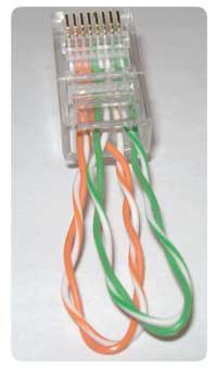
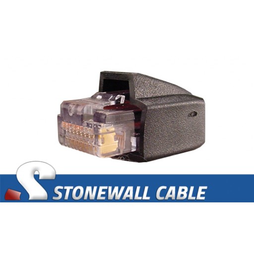
The modem will use pin 1 (CD – Carrier Detect) to tell the computer that there is a carrier tone detected or it has made a connection with a second modem. Loopback can combine audio from both application sources and audio input devices, then make it available anywhere on your Mac. When you attach a model to a data source backed by one of the database connectors, the model automatically acquires the create, retrieve, update, and delete methods from PersistedModel. It is important to understand the purpose of each connection for troubleshooting serial connections. LoopBack database connectors implement create, retrieve, update, and delete operations as a common set of methods of PersistedModel. The above tables and wiring diagram outlines the required connections to create a loop back plug.


 0 kommentar(er)
